Team 4698 Test Bench Exercises
Test Bench
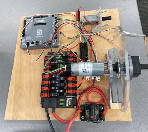
The Test Bench was created to allow students wanting to learn FRC robot programming a way to do example problems without needing access to a functioning robot. As you read these examples they will refer to terms and/or concepts that will not be familiar to you. Stop and lookup what these unfamiliar terms/concepts mean as you go along.
The Test Bench uses a roboRIO and a CTRE Power Distribution Panel (clink on the links and read about these things!). It has two motors attached to it, a brushed motor (NeveRest with 40:1 gearbox) and a brushless motor (a NEO 550) connected to two different motor controllers (a SPARK and a SparkMAX). The SPARK motor controller is controlled with PWM and the SparkMAX is controlled over the CAN bus of the roboRIO.
The NeveRest motor connected to the large disc is used in the position control exercises and refered to as the "Position Control" motor. It is connected to the SPARK motor controller which is wired into the roboRIO PWM channel 1. The position control motor has a SRX Mag Encoder attached to its output shaft. The SRX is wired into the roboRIO DIO channels 3, 4, and 5. Channels 3 & 4 are the Quadrature A and B inputs and channel 5 is the absolute PWM signal.
The NEO 550 motor that is mounted on the short bracket is used in the velocity control exercises and refered to as the "Velocity Control" motor. It is connected to the SparkMAX motor controller which is connected to the roboRIO CAN bus with ID 1. The NEO 550 has a built-in encoder.
The Test Bench does not have a WiFi radio so the coding computer must be connected to the roboRIO with a USB cable (USB A to USB B). The Test Bench must also be powered by a robot battery.
Figure 1. The Test Bench
Simple Motor Percent Output
Creating a Blank Project
In this example we will be creating a "Timed Robot" program to set the position motor’s percent output based on the position of a controller joystick.
Launch "WPILib VS Code" from the desktop. This runs VS Code with the WPILib libraries and tools enabled. Follow these directions to create a blank project from the "Timed Skeleton (Advanced)" template or see the animation below.
You should now have an empty project. The two files that we will be working with are src/main/include/Robot.h and src/main/cpp/Robot.cpp. Find those files in the Explorer on the left sidebar of VS Code and open Robot.h. It contains the Robot class which declares (See Forward Declarations and Definitions) the Robot-, Autonomous-, Teleop-, Disabled-, Test-, and Simulation- Init() and Periodic() functions.
Figure 2. Create a Blank Timed Robot Project
Contents of Generated Robot.h
// Copyright (c) FIRST and other WPILib contributors.
// Open Source Software; you can modify and/or share it under the terms of
// the WPILib BSD license file in the root directory of this project.

#pragma once

#include <frc/TimedRobot.h>

class Robot : public frc::TimedRobot {
 public:
  void RobotInit() override;
  void RobotPeriodic() override;

  void AutonomousInit() override;
  void AutonomousPeriodic() override;

  void TeleopInit() override;
  void TeleopPeriodic() override;

  void DisabledInit() override;
  void DisabledPeriodic() override;

  void TestInit() override;
  void TestPeriodic() override;

  void SimulationInit() override;
  void SimulationPeriodic() override;
};
Adding Controller and Motor Variables
For this simple example we won’t need most of the Init() and Periodic() functions so delete all the declared functions except RobotInit(), RobotPeriodic() and TeleopPeriodic(). RobotInit() runs once when the code first starts, RobotPeriodic() runs every 20 milliseconds at all times, and TeleopPeriodic() runs every 20 milliseconds while the Driver Station is in TeleOperated Mode.
We need to add member variables to the Robot class for our motor controller and for a joystick. The motor controller on the position motor is a SPARK controller so we will be using the `frc::Spark` class. Open the `frc::Spark` class API documentation which will show what methods are available with the `frc::Spark` class and what header needs to be included to use the class. In the API documentation for `frc::Spark` only the constructor that takes the PWM channel is shown along with the default constructor and the assignment operator. Expand the Public Member Functions inherited from frc::PWMMotorController section to see more member functions that are available that are inherited from the frc::PWMMotorController class which is a base class of `frc::Spark` (See Object Orientation). In Robot.h add a private section to the Robot class that declares a `frc::Spark` variable and initialized the channel to one. Also add a frc::XboxController variable initialized to port zero. You also need to add the two header files that are needed for the new classes using the #include directive. The headers are <frc/motorcontrol/Spark.h> and <frc/XboxController.h>.
Robot.h after changes
// Copyright (c) FIRST and other WPILib contributors.
// Open Source Software; you can modify and/or share it under the terms of
// the WPILib BSD license file in the root directory of this project.

#pragma once

#include <frc/TimedRobot.h>
#include <frc/motorcontrol/Spark.h>
#include <frc/XboxController.h>

class Robot : public frc::TimedRobot {
 public:
  void RobotInit() override;
  void RobotPeriodic() override;
  void TeleopPeriodic() override;
 private:
  frc::Spark m_motor{1};
  frc::XboxController m_controller{0};
};
Setting up Controller—Motor Connection
The src/main/cpp/Robot.cpp file has the definitions of the Init() and Periodic() functions for the Robot class. Remove all the Init() and Periodic() functions except RobotInit(), RobotPeriodic(), and TeleopPeriodic(). Now add the line shown below to TeleopPeriodic() which sets the motor percent output (-1 to 1 value) to the value of the X-axis on the controller. You won’t use RobotInit() and RobotPeriodic() just yet.
Robot.cpp after modifications
// Copyright (c) FIRST and other WPILib contributors.
// Open Source Software; you can modify and/or share it under the terms of
// the WPILib BSD license file in the root directory of this project.

#include "Robot.h"

void Robot::RobotInit() {}
void Robot::RobotPeriodic() {}

void Robot::TeleopPeriodic() {
    // Set the motor percent output to the controller left x-axis value
  m_motor.Set( m_controller.GetLeftX() );
}

#ifndef RUNNING_FRC_TESTS
int main() {
  return frc::StartRobot<Robot>();
}
#endif
Build and Deploy to RoboRIO
The roboRIO is an embedded computer running a real-time linux operation system. In order to run the robot program, it much be built and deployed to the roboRIO using VSCode. There must be a link between the coding computer and the roboRIO. This link can be made in three ways, first the coding computer can be connected via USB to the roboRIO. Second they can be connected wirelessly if the roboRIO is connected to an FRC Wifi Radio OpenMesh OM5P-AC by connecting the coding computer to the hotspot created by the robot. Third they can be connected via ethernet by running an ethernet cable between the computer and the OpenMesh OM5P-AC or a network switch connected to the OM5P-AC.
Since the Test Bench does not have a radio we must use the USB connection. After connecting to the roboRIO the robot program can be built and deployed.
ADD BUILD/DEPLOY GIF
FRC Driver Station
The Driver Station program manages the connection between the computer and the roboRIO. It gives that status of the connection and whether joysticks are recognized. It is how the robot is Enabled and Disabled among other things.
| See the Driver Station Overview to learn about its features. |
|
Build the project with the above changes added and make sure there are no errors. Then connect to the test bench with a USB cable and power the test bench. Connect an Xbox controller or a Logitech controller to the your laptop and run the Driver Station. Deploy the code, select |
|
Adding an Encoder
We are going to add the built-in encoder to our program so we can see how much the motor has turned and how fast it is turning. In Robot.h, use the frc::Encoder class to declare a variable for the encoder on channels 3 and 4.
Changes to Robot.h
  // Add the following header:
#include <frc/Encoder.h>

...

    // Add a private member variable such as:
  frc::Encoder m_enc{ 3, 4 };
Visualizing What is Happening
The Shuffleboard program is used to communicate with the roboRIO. The roboRIO can send information to Shuffleboard and Shuffleboard can be used to send information to the roboRIO. The frc::SmartDashboard class is one method to communicate with Shuffleboard. We will use the static member functions of the frc::SmartDashboard class to add information about the motor and the joystick position to Shuffleboard.
C++ classes with static member functions are used like regular functions. You do not create instances of the class. See Static Member Functions |
Modify Robot.cpp to the following:
#include "Robot.h"
#include <frc/smartdashboard/SmartDashboard.h>

void Robot::RobotInit() {
  frc::SmartDashboard::PutData( "Velocity Motor", &m_motor );
  frc::SmartDashboard::PutNumber( "Encoder Distance", 0.0 );
  frc::SmartDashboard::PutNumber( "Joystick X-axis", 0.0 );
}

void Robot::RobotPeriodic() {
    // Get the current encoder distance and send it to the
    // SmartDashboard.
  double enc_dist = m_enc.GetDistance();
  frc::SmartDashboard::PutNumber( "Encoder Distance", enc_dist );
}

void Robot::TeleopPeriodic() {
    // Get the controller Left stick X-axis value
  double x_axis = m_controller.GetLeftX();

    // Send the value to the SmartDashboard
   frc::SmartDashboard::PutNumber( "Joystick X-axis", x_axis );

    // Set the motor percent output to the controller x-axis value
  m_motor.Set( x_axis );
}

#ifndef RUNNING_FRC_TESTS
int main() {
  return frc::StartRobot<Robot>();
}
#endif
|
Compile and deploy the code to the test bench. Run Shuffleboard and select the "SmartDashboard" tab. Move the motor disc by hand and observe the encoder value changing. Now select |
|
Encoder Values
The encoder values displayed on Shuffleboard are obtained with the frc::Encoder GetDistance() function. By default, encoders return distance in raw "counts" which can vary between a few counts per revolution up to 4096 or more depending on the resolution of the encoder. Approximate how many "counts" the encoder has per revolution by rotating the disc one full revolution (with the joystick) and determining the change in the distance measurement. For this motor the number of "counts" per revolution should come out to be 1024.
When programming the robot we want to work with more meaningful units than raw counts. If the mechanism is an arm that will move less than a full revolution then we probably want to use degrees. If the mechanism is a spinning flywheel then we probably want to use revolutions. The frc::Encoder class has a member function called SetDistancePerPulse() which allows you to change the units returned by the GetDistance() function.
Make the following modifications to the RobotInit() function to make the encoder return distance in rotations:
Changing Encoder Units
    // Add SetDistancePerPulse() function call to RobotInit()
    // Converts a 1024 count per revolution encoder to read rotations
  m_enc.SetDistancePerPulse( 1.0 / 1024 );
|
Deploy and run the robot code with the |
|
Position Control Exercise
The Percent Output exercise (Simple Motor Percent Output) above is the most simplistic way of controlling a motor. Percent output control cannot perform the kinds of control that are needed for almost all robotic systems. This project will move a motor to a specified position and hold it there. It will use P-control (position-control) to maintain the desired position which is a feedback control algorithm.
If you haven’t already, read the Motion Control section and watch the "PID Video, Part 1" in the first part of that section. This example builds on the project that was created in Simple Motor Percent Output so you will need the code from that project. If you have used the SetDistancePerPulse() function as outlined in Encoder Values then comment out the function call so that the encoder reads "counts".
P-Controller
The video in the first part of the Motion Control section does a good job of describing what a P-controller does but I will reiterate it here. The idea is to measure the current position of the robot mechanism (y) and then take the difference between the desired position (r) and the current position (y), this is the current position error (e). We then set the motor percent output to the error (e) multiplied by a constant (Kp) to scale things correctly.
Add code to hold the position 0 while the A Button is held down and then move to the position 500 when the B button is held down. When neither button is held then it should just stop the motor. The pseudocode for this is expressed as:
Pseudocode for P-Controller
    If Button A is held::
      error = 0 - {encoder position}
      set motor output to (Kp * error)
    Else If Button B is held::
      error = 500 - {encoder position}
      set motor output to (Kp * error)
    Else
      set motor output to zero
    End If
This logic will go in the TeleopPeriodic() method. A good starting value for Kp is to take the total distance that the motor has to move from one setpoint to the other (500 in this case) and take the inverse of that number ( 1.0 / 500 ). So as a first guess, the value of Kp should be 0.002.
|
Implement the above pseudocode for the P-controller. Change the value of the Kp constant and observe the difference in behavior of the mechanism. Note whether the actual position gets exactly to the desired position (setpoint). |
|
Sending Data with Shuffleboard
Not only is possible to send data from the robot program to Shuffleboard but also to send data back to the robot. The changing of the Kp constant in the above situation is a perfect example of when using Shuffleboard to send data to the robot is helpful. If we can send the Kp value to the robot while it is running then we do not need to change the code / compile / deploy just to change one constant. Above we used the PutNumber() method of the frc::SmartDashboard class to send a number to Shuffleboard. There is a corresponding GetNumber() method that will read a number from Shuffleboard. If we create a Shuffleboard entry in RobotInit() for the Kp value then we can read that value in TeleopPeriodic(). This way the value can be changed in Shuffleboard and it will use the new value in TeleopPeriodic().
|
Change the code so that the value of the Kp constant is read from Shuffleboard and therefore can be set while the robot code is running. |
|
Shuffleboard Graphs
Read the Shuffleboard documentation and in particular Working with Graphs.
|
Graph the desired position (setpoint) and the actual encoder position in a |
|
|
Modify the units returned by the encoder as demonstrated in Encoder Values to use rotations. Have Button A still go to 0 but change Button B to go to 2 rotations. |
|
AdvantageScope
AdvantageScope is a NT viewer and a Log File viewer that is much more powerful than Shuffleboard. It’s graphs are far superior and much easier to use. Do the graphing exercises above using AdvantageScope rather than Shuffleboard. Explore the AdvantageScope Docs to see all of its available features.
Relative Encoder Limitations
Relative encoders consider the "0" position to be wherever the motor was when the encoder was powered on. Therefore it is not possible to know where the "0" position is and it changes each time the robot is powered on.
|
Note where the encoder considers the zero positon. Disable the robot and manually move the position motor to a new position then restart the robot code by going to |
Absolute Encoder
So far we have been using the relative quadrature output of the SRX Mag Encoder. The encoder also has a PWM signal for absolute positioning (See SRX Mag Encoder Hardware Guide). The frc::DutyCycleEncoder class is used to interface with the PWM absolute position signal which is wired to the DIO channel 5.
|
Modify the code to read the SRX Mag Encoder's absolute PWM signal using the |
|
Physical Units
The absolute encoder PWM signal is reading in "counts" just like the relative encoder signal did in Encoder Values. In this case the absolute signal has a larger number of "counts" per rotation that the relative signal. As before, it is much more useful to use some physical units with the encoder.
|
Modify the code to move to locations based on angles in degrees when the A and B Buttons are pressed. You will need to determine how to configure the |
Velocity Control Exercise
Velocity control is typically used on flywheels for shooting mechanisms or sometimes for intake wheels for game pieces. Using velocity control may seem like essentially the same as setting a motor’s percent output. However, velocity control reads the speed that the motor is actually spinning and makes corrections if the speed is wrong whereas percent output does not check for the correct speed. This becomes important, for example, when the battery voltage drops while the robot is running during a competition which will cause a motor set to a percent output value to slow down.
There is a very good description of controling a flywheel mechanism in the link below along with some interactive tools to see how changing the control system parameters affects the flywheel behavior.
REVLib
We will use the velocity motor (NEO 550) that is connected to the SparkMAX motor controller for this exercise. The SparkMAX uses the CAN bus of the roboRIO and requires an external (vendor) library to function. Vendor libraries can be added to a project following these instructions. You need to add the "RevLIB 2023" library to this project in order to use the SparkMAX controller.
The rev::CANSparkMax class is used to communicate with the SparkMAX controller. The rev::CANSparkMax is not part of the WPILib library and was added when the REVLib vendor library was added to the project in the steps above. Therefore the documention for the rev::CANSparkMax class and other classes that are provided by the REVLib library are located on the RevRobotics website. The Resources section of the Coding Guide gives links to the RevLib documentation, RevLib C++ API, and RevLib Examples. The Resources section also has several other useful links.
Velocity P-Control
| Read the Motion Control section (again). |
The SparkMAX is assigned CAN id #1 on the CAN bus. In Robot.h, create a variable for the motor using the rev::CANSparkMax class. You will need to determine what header file is needed to use the class. The rev::CANSparkMax Set() method will be used to control the motor percent output. Use the rev::CANSparkMax GetEncoder() method to access the built-in encoder on the NEO 550. The GetEncoder() method returns a rev::SparkMaxRelativeEncoder class object that can be used to retrieve the motor velocity (what method?).
|
Write a program to spin the NEO 550 to 9000 RPM when the A Button is held down. Use P-control on the motor velocity. Graph the setpoint and actual velocity in Shuffleboard. |
|
Feed Forward
| Read the Feed Forward section and, if confused, read the Motion Control section a third time and the above WPILib information. This topic is confusing at first and you may need to re-read these sections several times. |
Feed forward predictions are typically expressed in units of voltage. P-control on the otherhand is usually giving you a corrective error in percentage units. When using feed forward it is most common to use the motor controller class' SetVoltage() method if one exists.
|
Modify your program to spin the NEO 550 to 9000 RPM when the A Button is held down using velocity based feed forward only. |
|
Feed Forward with P-control
Typically a motorized mechanism would be controlled with both some form of feed forward combined with PID feedback to compensate for any error. The PID values (-1 to 1) are usually scaled to voltage (multiply by 12) and then the two terms (FF and PID) are added and sent to the SetVoltage() method.
|
Modify your program to use both feed forward and P-control. |
|
Built-in WPILib Classes for Control
|
Use the |
Trapezoidal Motion Exercise
In Position Control Exercise if the current motor position was very far from the desired position, then the motor would be immediately set to full power (100% output) toward the new desired position. This results in very abrupt and jerky movements of the mechanism. A better way to move the motor is to smoothly accelerate the motor towards the goal position until we reach a "cruise" velocity and then as we get close to the goal position we smoothly decelerate to a stop. This type of motion is called a trapezoidal motion profile because the plot of the velocity during the motion is a trapezoid.
The term goal is emphasized because it differs from the setpoint that we have been using up until this point. The way profiled motion works is that at each timestep the trapezoid profile computes a new setpoint. The setpoint has both position information and velocity information. The profiled motion is finished when the setpoint reaches the goal. Because the setpoint has position and velocity information, it is fairly straight forward to use feed forward and PID control while performing a profiled motion.
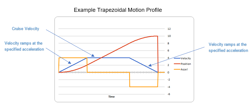
Figure 3. Trapezoid Profile (from CTRE Docs)
The WPILib provides the frc::TrapezoidProfile<Distance> class to generate a trapezoidal motion profile. It is a template class templated on either an angular unit or a distance unit. The WPI Documenation describes using trapezoidal motion profiles.
|
Write a program to use a trapezoidal profile to move the position motor disc to a 0 degree position when Button A is pressed and 180 degrees when Button B is pressed. Use P-control, then add feed forward once P-control works. |
|
Arm Control Exercise
A vertical arm mechanism is one of the most complex control problems that is encountered on FRC robots. The links below give the basic information needed to understand the feed forward and PID aspects of the problem. Moving a vertical arm with motion profiles (i.e. trapezoidal profiles) gives good results and allows easy feed forward compensation.
|
Write a program to use a trapezoidal profile to move the position motor disc with the added weight blocks to a 0 degree position when Button A is pressed, 90 degrees when Button B is pressed, and 180 degrees when Button Y is pressed. Use both feed forward and PID control. |
|
Command Based Exercise
So far all the exercises have used the "Timed Robot" design pattern. When the robot code needs to respond to multiple button presses and joystick positions the logic in the TeleopPeriodic() function can get very busy with multiple if … else statements. The "Command Based" design pattern removes the need to worry about the button press and joystick logic. It also forces the programmer to break down their code into multiple files containing logically related information which results in better program organization.
In the Command Based design pattern, controller buttons and axes are "bound" to commands. When the button (or axis) is pressed the bound command is executed. The underlying command scheduler takes care of determining if the button is being pressed and calling your command if it is. One of the more difficult to understand aspects of Command Based programming is the use of Lambda Expressions and the idea of treating "functions as data" (i.e. passing functions as paramters to other functions). In Command Based programming lambda expressions occur frequently for simple commands that are bound to a controller button.
| See Command-Based Programming and Functions as Data particularly Lambda Expressions in C++ |
Create a blank project using the "Command Robot" template. Browse the files that are automatically generated. The directory structure is a bit more complicated than the "Timed Robot" projects that you have been working with so far. There are still the Robot.h and Robot.cpp files but there are several more files created. The Command Based design pattern compartmentalizes the project into several files that each contain code for distinct parts of the project. The RobotContainer.cpp file has all the subsystems in it. The subsystems folder contains all the subsystems for the robot and the `commands folder contains all the commands needed for the robot.
|
Write a command based program to control the velocity motor. When the |
|
Commands that are bound to a joystick button only execute when the button is pressed (or held etc). Usually during TeleOp mode a robot program needs to respond to joystick input at all times (such as driving the robot around). This is accomplished with the default command of a subsystem. Each subsystem can have a different default command.
|
Modify the command based program to control the velocity motor such that the right trigger varys the speed of the motor from 0 to 6000 rpm. |
|