Overview

The Design Sub-Team is responsible for the CAD/CAM designs used to build the robot. In order to make good designs it is necessary to understand the manufacturing and mechanical sub-team’s jobs very well. It is quite challenging to make a design that is easy to manufacture, easy to assemble, and easy to maintain.

The design process is an iterative process. Designs evolve and change during robot building and testing.

We use Autodesk Fusion 360 as our design software. Each season we create a new Project that is used for all of the design files. It is important to keep the project directory organized with folders that contain the components for each logical sub-component of the robot (i.e. frame base, drivetrain, arm, intake, turret, etc.). There is also a Vendor folder that contains some of the 3D models from the various vendors we use for Commercial Off-The-Shelf (COTS) items organized into subfolders.

Fusion 360

Learning Fusion

Try to learn as much as you can in order to efficiently and effectively use Fusion 360. This means practice by doing some examples, watch the tutorial videos from Autodesk, and ask questions when you are struggling.

7 Tips for Organizing Bodies & Components discusses the key idea of activating a component before doing any operations on the component to make the timeline cleaner and better organized.

There some CAD exercises on ChiefDelphi structured like the 24 days of an advent calendar.

Also checkout the Fusion 360 Blog for other tips and tricks.

Sketches are Key

Sketches are the most important part of Fusion to master when you are just learning. In particular the efficient use of constraints and dimensions will help make designs easier to modify in the future.

ALL SKETCHES MUST BE FULLY CONSTRAINED. DO NOT USE THE LOCK CONSTRAINT.

Fully constrained sketches force you to consider all aspects of the geometry of the sketch and make modifying the sketch later much easier.

Use construction lines when necessary. They are sometimes easier than using dimensions for overall positioning. When a part must mate with another, project only the geometry necessary to align the two parts.

Sketch Exercise 1

Design a plate 4in x 2.5in x 0.25in with the mounting hole pattern for a RevRobotics NEO motor in the center such that four bolts can be used. Do this exercise without downloading the STEP model of the NEO, look at the NEO drawing to find the dimensions. Use a close fit clearance hole size for the motor mount bolts (see Fasteners and Drill/Tap/Clearance Hole Chart).

Motor Mount
GOALS:
  1. Practice making a simple sketch and using constraints.

  2. Learn how to look at the motor/part drawings to get dimensions needed for designing.

  3. Think about fasteners and the correct hole sizes for them.

QUESTIONS:
  1. Is your sketch completely constrained (no blue lines)? Do NOT use locking (green lines).

  2. Would this hole pattern work for a Falcon 500 motor with least four bolts attaching the motor? Kracken motor? If not, what changes would have to be made to be able to use either a NEO, Falcon or a Kracken?

  3. Redo this exercise using the STEP model of the NEO and projecting the necessary geometry to the sketch plane. Position the NEO into the correct location against the mount.

Using Vendor 3D Models

Most of the FRC parts the are used on the robot have 3D model files of the item available (STEP files). The Vendor folder in the Project directory contains the models that have been downloaded. If you need to add an item that isn’t there then put it into the correct subfolder and use a file name that makes sense. For example, 1/2" Hex Rod from WCPs website might be named HEX_ROD_0500_WCP_217-2753 which tells everyone what it is, where it was downloaded from, and the part number(look at the other items there for other examples). Do not modify the vendor files directly. If you need to modify a part (e.g. shorten hex rod) then insert the component into your design and break the link between it and the vendor file. It can then be modified without changing the original vendor file.

Fasteners can also be inserted directly into a design using the Insert → Insert McMaster-Carr Component command. Search for the item you need on the McMaster-Carr website that pops up and then select "3D STEP" as the file type and click Download. McMaster-Carr has many types of fasteners including nuts, bolts, washers, e-clips, hex keys, etc.

Moving and aligning imported components is done by rotating the component to the proper orientation then using a Point-To-Point move to get the component to the correct X,Y,Z location. It is usually easiest to select circles (or arc centers) as the source and target "points".

Vendor Exercise 2

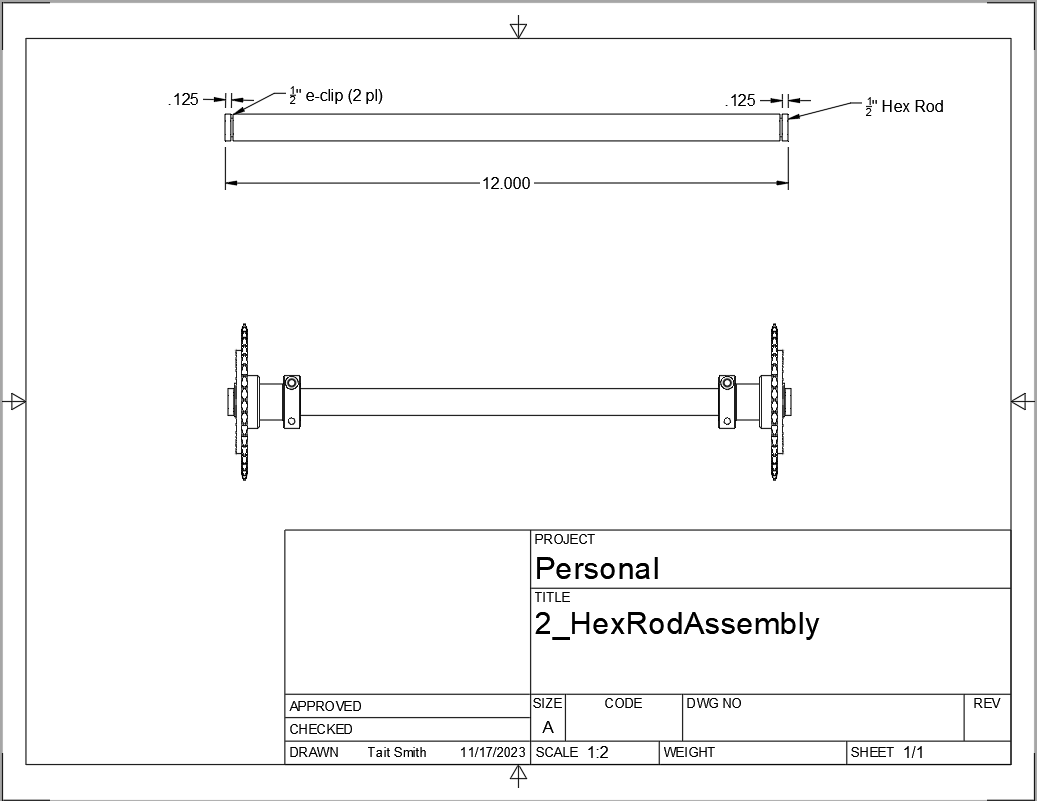
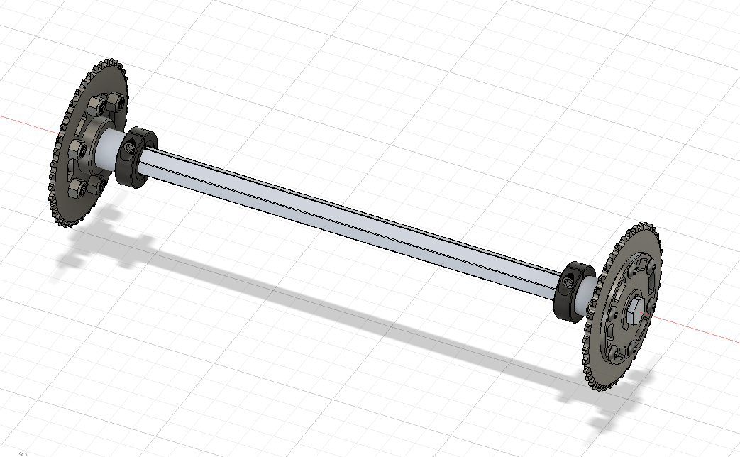
Design a hex rod shaft with a 40 tooth chain sprocket on each end as shown in the drawing below. Get the FRC specific part files from West Coast Products and use a Vendor folder to store your vendor models. Use meaningful names for your files within your Vendor folder (see above). You will need part numbers 217-2753, 217-2637, WCP-0790, WCP-0324, and 217-2592. You will also need e-clips and bolts from McMaster-Carr. McMaster-Carr parts can be inserted directly from within Fusion 360.

Hex Rod Asmb
Hex Rod Asmb
GOALS:
  1. Learn how to break the link to a Vendor part for modification.

  2. Learn how to position inserted designs into the correct location.

  3. Learn how to insert McMaster-Carr parts into a design.

QUESTIONS:
  1. What did you have to sketch for this design?

  2. Did you draw the hex rod or use the Vendor model and shorten it?

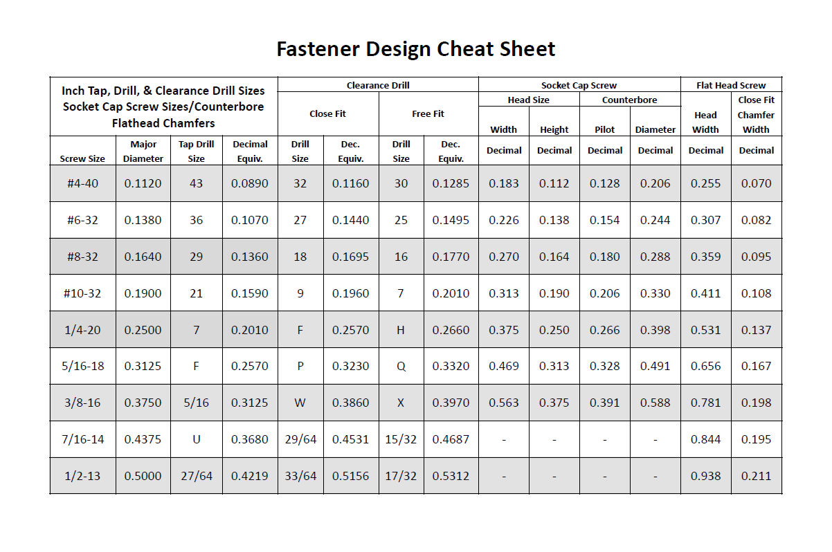
  3. How did you determine the fastener sizes needed?

  4. How did you determine the e-clip groove dimensions?

Components in Fusion 360

Unless you are making a single part made of a single body you should create components for each part of your design AND BE SURE TO ACTIVATE that component when you are working with it. Most of the advanced functionality of Fusion 360 only works with components such as joints and rigid body constraints. Activating a component before doing any operations on it will filter the timeline to only those that pertain to that component which makes working with the timeline much easier as designs get complicated.

Multi-Component Robot Organization

Each part of the robot should be designed (CAD and CAM) in its own design file. The complete robot is then assembled from the individual component design files. It may make sense for some design files to contain multiple components but generally having a single component per design file makes compartmentalizing the CAD and particularly the CAM elements easier.

Mechanism Motion Design

Belts, Chains, and Gears are commonly used on FRC robots. When a design uses these elements it is possible to choose the distance between rotation centers such that exact lengths of belts or chains work correctly. Gears will not work without precise center-to-center distances. A great deal of very good information can be found in the WCP FRC Build System documenation.

Belt Drives

Belt drive systems are a quiet and relatively safe means of transferring rotation between shafts. FRC belts are either 5mm HTD belts or 3mm GT2 belts, where the distance represents the pitch of the belt teeth. They also come in either 9mm or 15mm widths. Belt pulleys don’t come in as many tooth count options as chain sprockets or gears which limits the gear ratios available.

The center-to-center distance for a belt system can be calculated with the ReCalc Belt Calculator or with the WCP Belt Calculator.

Chain Drives

Chain used in FRC comes in a smaller size (#25) and a larger size (#35). Chain drives are strong but noisy and dangerous (can cut off fingers easily). Chain sprockets come is a fairly good range of sizes with the larger sprockets having a VersaHub bolt pattern rather than a 1/2" Hex bore. Chains have a tendancy to stretch and loosen slightly over time. ReCalc has a Chain Length Calculator.

Gear Drives

Gears come in many tooth counts (every 2 tooth increments) and the larger sizes are 1/2" Hex bore (unlike chain sprockets). The center-to-center distance can be found with the WCP Gear Calculator.

Once a center-to-center distance is found for a pair of gears, any gears that sum to the same tooth count will work for that center-to-center distance. For example if you find the center-to-center distance for a 16T gear meshing with a 44T gear then you can take the sum of the tooth counts (16T + 44T = 60T). Now any pair of gears that sum to 60T will work with that center-to-center distance (e.g. 24T and 36T). In the technical drawing for the WCP Rotaiton SS Gearbox you can see that this sum is specified for each stage of the gearbox.

The smallest gears that mount on motors (motor pinions) come with smaller tooth counts but the same center-to-center distance. This is called addendum modifying the gear (see Addendum Modified Gears) and it allows several motor pinion gears to be used with the same gearbox without modifying the driven gear that the motor pinion is mating with.

Gearbox Exercise 3

Design a 2-stage vertical oriented gearbox with a 16:1 ratio that uses a Falcon 500 motor and has a 1/2" Hex output shaft. Have the gearbox bolt to a 1"x1" tube. You will need to have the plate spacing at 1-1/8" in order for flange bearing to fit inside the plate. This design is very similar to the WCP Rotation SS Gearbox but in the vertical orientation. Don’t use the WCP 3D model, start from scratch.

Gearbox Sketch
GOALS:
  1. Learn how to correctly space gear shafts.

  2. Learn about multi-stage gearboxes.

  3. Practice creating multiple components and activating them to organized the timeline.

QUESTIONS:
  1. This is a fairly complex design. What problems did you run into?

  2. Did you create multiple components and activate them to separate out the timeline?

Gear Ratio Calculation

The gear ratio that is needed for a mechanism can be calculated using the Motor Power Curve for the motor that will be used along with the mass of the mechanism. The goal is to utilize the more efficient parts of the Motor Power Curve which means keeping the speed of the motor fairly close to the middle of the RPM range (Figure 1).

NEO Motor Power Curve
Figure 1. NEO Motor Power Curve showing the peak power at ~2900 RPM.

Online calculators are very helpful in determining the correct gear ratio for a mechanism. The AMB Robotics Calculators has a calculator for "Mechanism Ratios" that will determine the best gear ratio for the given mechanism geometry and weight.

Mechanism Exercise 4

Determine the correct gear ratio to use for a Climber mechanism to lift a 145 pound robot with a single NEO Vortex motor. Use the AMB Robotics Mechanism Calculator. The motor should stay below 40 amps.

Climber Sketch
GOALS:
  1. Learn how to use the mechanism ratio calculator.

  2. Learn how to read a Motor Power Curve.

QUESTIONS:
  1. How long will a 15" climb take?

  2. How could you speed up the climber?

Fasteners

Design team members must understand the various fasteners available. Designs need to take into consideration clearances for fasteners and fastener heads. Designs also need to specify the correct hole sizes for holes that will be threaded or for bolt clearance.

Details of fasteners are given in Mechanical Sub-Team — Fasteners

Fastener Cheat Sheet
Figure 2. Dimensions used in design for commonly used fastener sizes.

Computer Aided Manufacturing (CAM)

Making complex designs using a CNC machine (i.e. the ShopBot and the HAAS) requires creating instructions for how the cutting tools must move. Those instructions are "post processed" into a NC program file that the CNC machines read. Fusion 360 can be used to create the machining tool paths and convert them to NC programs.

A great resource for learning CAM modeling is the Titans of CNC Building Blocks Series. This series gives both CAD and CAM instructions for creating parts and generating the NC program. Students in Engineering II sometimes make the Titan-4M part. If you have good CAD skills then it is useful to only look at the drawing PDF and generate the CAD model from the PDF. Then watch the video on how they created CAD model. They sometimes use different techniques which gives you an alternative method of doing the same thing.